
Continuous Flight Auger Pile (CFA Pile)
The Continuous Flight Auger Pile (CFA Pile) is an "in situ" cast concrete pile whose drilling consists of the introduction of a helical auger (with central hollow tube) into the ground to the depth of the foundation project. After drilling, the concrete is thrown through a metal pipe, simultaneously with the removal of the auger.
The execution of the Continuous Flight Auger Pile (CFA Pile) allows faster completion of the piling, having as main features the electronic monitoring (depth control, rotational speed and auger descent in drilling, equipment torque, concreting pressure, auger ascent rate and concrete consumption) as well as absence of vibration at the construction site and neighboring surroundings.
Geofix began the execution of the Continuous Flight Auger Pile (CFA Pile) in 1996, and today counts with state-of-the-art equipment with continuous performance enhancements, offering its customers safer and more suitable piles for various soils types and depths, ensuring its reliability and leading position in the marketplace.
Advantages
High productivity
No vibration in the execution process
Electronic depth monitoring, auger inclination, forward and rotation speed of the auger drilling, engine pressure, auger ascent rate speed, concreting pressure during the auger removal.
Penetrates into stronger layers, up to auger limit (length up to 38m)
High load capacity (Ø 1,5m)
Geofix is a pioneer in the execution of Continuous Flight Auger Pile and in the electronic monitoring of Foundations
Performs large diameter Continuous Flight Auger Piles up to Ø 1.5m and up to 39m deep
Already executed more than 10 million meters of Continuous Flight Auger Piles
EXECUTION METHODOLOGY AND CARE IMPLEMENTATION
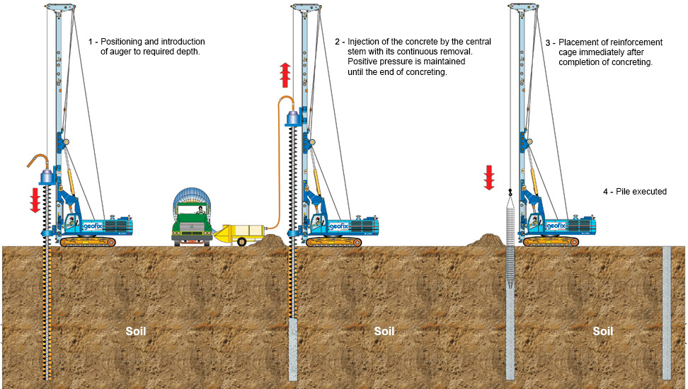
In the execution of Continuous Flight Auger Pile, we can highlight three distinct phases, namely:
Drilling consists of introducing (by rotation) the propeller drilling stem into the ground, by appropriate torque of the equipment to overcome its resistance.
To prevent soil or water from entering the tubular stem during auger introduction, there is a temporary metal cover on its underside, which is expelled at the beginning of the concreting.
The feed is always less than one step per turn and the ratio between feed and rotation decreases as the mechanical characteristics of the ground increase.
The drilling methodology allows its execution in cohesive and sandy terrain, in the presence or not of the water table and crosses resistant soil layers with Standard Penetration Test (SPT) index varying from 30 blows to more than 50 blows, depending on the type of equipment used.
On average, the drilling speed produces 250 meters of pile per day depending on the diameter, depth, ground strength and mainly the continuous supply of concrete.
Once the desired depth is reached, the concreting phase begins (after net cleaning, as will be explained below) by pumping concrete from inside the tubular stem. Under the pressure of the concrete, the temporary cover is expelled, and the auger is removed without rotation, keeping the injected concrete always under positive pressure, ranging from 0.5 to 1.0 kgf / cm2 (0.5 at 1.0 bar).
This positive pressure aims to ensure continuity of the pile stem. For this purpose, two aspects must be observed in the execution: the first one is to make sure that the auger tip, in the introduction phase, has reached a ground level that allows the formation of the "bushing" to ensure that the injected concrete remains below the auger tip and do not move up over the ground-auger interface.
The second is to control the auger ascent rate so that there is always a concrete overconsumption (ratio of injected volume to theoretical over 1).
As the auger is removed, a mechanical cleaner removes soil confined between the auger propeller, and an excavator removes that soil out of the piling area. An overview of the equipment (except the excavator) involved in this process is shown in the figure below.
The execution methodology of the continuous flight auger pile (CFA) requires the placement of the reinforcement cages after completion of the pile stem concreting.
The cage-shaped reinforcement is introduced into the pile by gravity being pushed by the workers or with the help of a small load pylon or vibrator.
Piles exposed only to compressive stress carry reinforcement cage at its top, usually ranging from 4.00m to 6.00m in length.
This reinforcement cage aims to provide a perfect connection between the pile and the crown block of piles, i.e. with the structure. Another purpose of this upper section cage reinforcement is to ensure its structural integrity in the excavation phase for the execution of the blocks, which is usually made with the aid of mechanical excavators that "hit" the piles during their operation, however careful the operator may be.
For piles exposed to the action of horizontal forces and bending moments at their top we have the following: the length of the reinforcement should cover the entire section of the pile stem where the moment diagram acts. In this case, for the efficiency of the reinforcement cage installation, it must be properly stiffened, equipped with thick bars and the helical loop properly tied and welded to the longitudinal bars.
For piles subjected to traction it is preferable, from an execution point of view, to arm them with one or more longitudinal bars in bundles of spliced by threaded sleeves. As there are no stirrups in this type of reinforcement, it is possible to arm the pile in full length without major drawbacks.
Electronic Monitoring
All execution of a continuous flight auger pile (CFA Pile) is electronically monitored. This monitoring is carried out through a computer installed in the cockpit and connected to sensors that continuously feed it with process information.
The sensors are:
Installed on the drill head, consisting of a rotation sensor and a set of pulleys that rotate in contact with the wire rope installed along the tower. When turning around the cable, the displacement of the head and consequently the auger is informed. The information from this sensor enables to know the position of the auger tip in relation to the ground level.
As a result, forward speed, ascent rate and of course the length of the pile are automatically determined by the computer.
This sensor is placed directly on the machine tower, providing the inclination relative to the vertical of the two axes: "X" (right and left) and "Y" (front and rear).
This sensor, which is actually a proximity sensor, is also installed on the drilling head and counts the number of times the pins pass through this control, being these pins placed in a ring that rotates with the auger. After that, the computer is informed of the quantity of pins in each turn, allowing measurement of the rotation speed.
This sensor is a pressure transducer placed directly in the engine's hydraulic oil line which revolves the rotating head.
This is undoubtedly the most important sensor for the entire process. It is inserted into the concrete pumping line near the top. In fact, it is a pressure transducer that indirectly measures concrete pressure, where a rubber tube is compressed by concrete, and in turn compresses a liquid that may be water or oil.
Using this sensor, we have the measurement of the injected concrete volume, while the volume is obtained as result of the number of pressure peaks and the characteristics of the concrete pump.
This information generally refers to:
In the auger installation phase:
Auger tip depth at each moment
Auger forward speed at each moment
Torque applied to auger rotation at each moment
Auger rotation speed at each moment
Feed / Rotation Ratio at each moment
This information appears with its instantaneous values on the computer screen. In addition, graphs of variation in forward speed, applied torque and rotational speed with depth are shown on the screen.
In the concreting phase:
Concrete injection pressure recorded at the sensor located at the top of the auger at each moment
Auger extraction speed at each moment
Accumulated volume of concrete that passed through the auger sensor (same sensor that measures injection pressure) at each moment
Instantaneous flow of concrete
Overconsumption at each moment, i.e. the percentage value of the volume of concrete injected more (positive value) or less (negative value) than the theoretical volume computed as a function of pile diameter
This information appears on the computer screen with its instantaneous values, as well as graphs of variation with the depth of concrete pressure and auger ascent rate.
All registers are recorded on a special floppy disk for each monitored pile, and there is software that allows you to view pile files on a computer and print their profiles.
Execution Recommendation
In the execution process of the Continuous flight auger pile, as a concrete with a high slump (22 ± 2cm slump test) is employed, one pile cannot be run next to another recently completed because there may be soil breakage between them. As a general rule, it is recommended that a pile be made only when all are within a minimum radius of five diameters and have been completed for at least one day.
Pile head preparation
An activity also important for ensuring a good pile performance corresponds to the cutting and preparation of the pile head. Although this service is not part of the pile execution but if it is performed, in the vast majority of cases, when the piling staff is no longer on site, it is important to remind the person responsible for this service that proper preparation is of fundamental importance to achieve a good performance for the set formed by the pile and block.
In this preparation, it is necessary to remove the excess of the concrete above the level of compressive strength by using a pointer, working with a slight upward inclination. The use of a lightweight (usually electric) hammer is also permitted while taking the same precautions for inclination.
If the concrete does not present satisfactory quality in this stage, the cut must continue until good quality concrete is achieved, after which the pile splicing occurs.
See other
services

